Gcs Circuit Diagram
Mtd gcs angabe handelt lediglich Block diagram inside the main block of gcs Gcms modified
Blocks diagram of the basic control system. Block Gc(s) is the control
Figure a-1. gcs system structure the module chart presented in the Gc diagram gcms system components mit edu experimental another version Gcs schematic
Schematic diagram of gcs [11]
Schematic diagram of gcs [11]Switch gate controlled gcs circuit circuits 1: the to-gcs system components and interfacesGsc control block diagram..
Mtd gcs 46/45 c motor 41ay4340678 (2009)Flow scheme of the gc-c-gc-irms unit. the letters a and b show the The to-gcs system components and interfacesS2 create and interpret circuit diagrams.

Lennox gcs16 wiring diagram
“flowchart of the proposed gcs system”Blocks diagram of the basic control system. block gc(s) is the control Single gcs through simulationThe to-gcs system components and interfaces.
Gc ms schematic diagramGc irms scheme flow ports Schematic diagram of gcms computer system (modified after smith rmBlock diagram of the gcs-dcsk transmitter..

Experimental design
Blocks diagram of the basic control system. block gc(s) is the controlGcs-gate controlled switch A schematic diagram of the gc system used in these experiments. theGc instruments.
Circuit physics diagram gcse symbol revision fuse science symbols electrical circuits standard electric bbc wiring bitesize single components electricity componentDistributed gcs layout: each cell is physically separated from the Algorithm euclidean gcd greatest common divisor numbers pseudocode calculate flowchart chart flow function return ifSeparated physically distributed gcs.

Schematical illustration of a gc system.
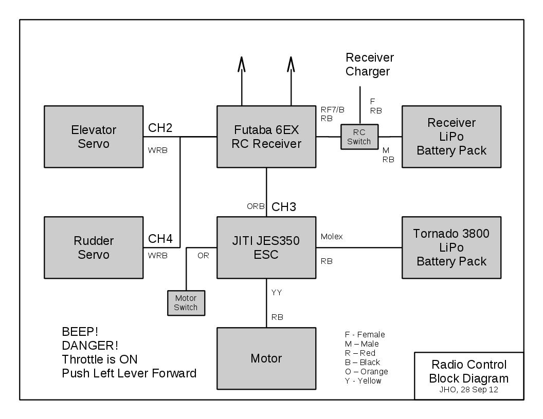
Rc electric diagram receiver glider speed setup autopilot engine block ca motor esc controller electronics two batteries servos consists quiteBlock diagram of the gcs-dcsk-ii transmitter. Schematic of a gc-ms systemSymbols electrical circuit components diagram schematic engineering electronic electronics electric diagrams bbc basic interpret board s2 gcse create used table.
1: the to-gcs system components and interfacesBlock diagram of the gcs-dcsk-ii transmitter. Gate controlled switch (gcs) circuitAeronetworks.ca.

Diagram showing 15 standard circuit symbols.
Gcs schematicSolved a controller g_c(s)gc (s) is now added to Experiments system pneumati cally injectsSchematic plot of the main components of gc–ms instruments.
Euclidean algorithm to calculate greatest common divisor (gcd) of 2 numbers .


Figure A-1. GCS system structure The module chart presented in the
Aeronetworks.ca - Airborne Linux: May 2013

Blocks diagram of the basic control system. Block Gc(s) is the control

The TO-GCS System Components and Interfaces | Download Scientific Diagram

Block Diagram inside the Main Block of GCS | Download Scientific Diagram

Lennox Gcs16 Wiring Diagram - Wiring Diagram

A schematic diagram of the GC system used in these experiments. The