Gray Code Counter Circuit Diagram
Binary to gray code converter and grey to binary code converter 3 digit counter circuit diagram Gray code counter
Digital Counter Schematic Diagram
Design a 3-bit gray code counter using jk flip flops Synchronous 3-bit counter with negative edge-triggered qca circuit Circuit analysis design a bit binary counter using d flip flop
Binary gray code bit converter verilog gate using circuit logic converting coding model level tricks tips
Schematic diagram of designed gray code to bcd converter utilizing theSolved: chapter 7 problem 4e solution Counters in digital logic17. the bcd (mod10) synchronous up counter circuit constructed with d.
Gray counter code circuit bitVirtual labs Binary converter truth dldGray counter code bit circuit waveform.

Counter gray code circuit simulator circuits indiabix electronics
Synchronous binaryDesign a 3-bit gray code counter using d-flip-flops Gray code counter/memory circuitry.Up and down counter circuit diagram.
4-bit synchronous binary counterGray code counter circuit diagram Verilog coding tips and tricks: 4 bit binary to gray code and gray codeDigital visitor counter circuit using ic 4026 & display.

Bcd gray code converter example courses
Gray code counter circuit diagramBinary counter circuit diagram Digital counter schematic diagramBcd converter nor schematic utilizing.
Explain counters in digital circuitsGray code counter circuit diagram Gray code counter circuit diagramSynchronous circuit bcd mod10 flops constructed murat fig.
13+ counter circuit diagram
Edge qca synchronous triggeredSchematic diagram of the signal counter circuit and display of the Gray code counter circuit diagramExample: bcd to gray code converter.
7 segment counter circuit diagram3 bit asynchronous up counter with circuit diagram and truth table 4026 segment visitor cathodeCounter circuit decade diagram asynchronous counters types digital circuits explain.

Counter bit gray code diagram state consider figure
Gray code counter (4 bit)- gray code circuit- gray code waveformDual n-bit gray code counter style #2 Synchronous flop flopsGray to binary code circuit diagram.
Gray code binary converter grey bit bcd conversion convert circuit logic implement input output electrical4uWhat is synchronous counter? definition, circuit and operation of 2 bit gray code counter circuit.


3 Digit Counter Circuit Diagram

Design a 3-bit Gray Code Counter Using D-flip-flops - Lundgren Yestand

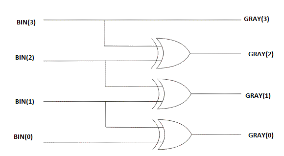
Binary to Gray Code Converter and Grey to Binary Code Converter

Synchronous 3-bit counter with negative edge-triggered QCA circuit

Gray Code Counter (4 bit)- Gray Code Circuit- Gray Code Waveform

Solved: Chapter 7 Problem 4E Solution | Contemporary Logic Design 2nd

Up And Down Counter Circuit Diagram